Recently there is growing interest in the USB DVB-T dongles used as a cheap SDR receiver. All started with introducing the FCD (FunCube Dongle) SDR receiver capable to receive the frequencies between 64-1700 MHz. Front end is basically one chip tuner developed for DVB-T receivers. Most popular among them is E4000. The FCD design was based on reverse engineering and HAM community start looking for the roots. Soon they discover that the same tuner has been used in variety of DVB-T tuners with affordable price and the "revolution starts"....
All kind of free software to control this DVB-T USB sticks were written and the community got the access to cheap receiving system that just a few years back cost from 1000-2000 $.
But.... the lack is that they can not tune efficiently bellow the 64 MHz where most of the HAM radio community is active, the HF bands. Some of the tuners can tune down to 30 MHz even lower but with a very poor characteristics. To overcome this problem a simple and basic approach in upconverter design was used.
The price of the DVB-T stick is quite popular so idea was to build the upconverter that can be also cheap but at the same time useful and practical to all users. This upconverter can be used together with all kind of software supported DVB-T SDR receivers, FCD or even normal VHF receiver to extend the frequency coverage on HF bands.
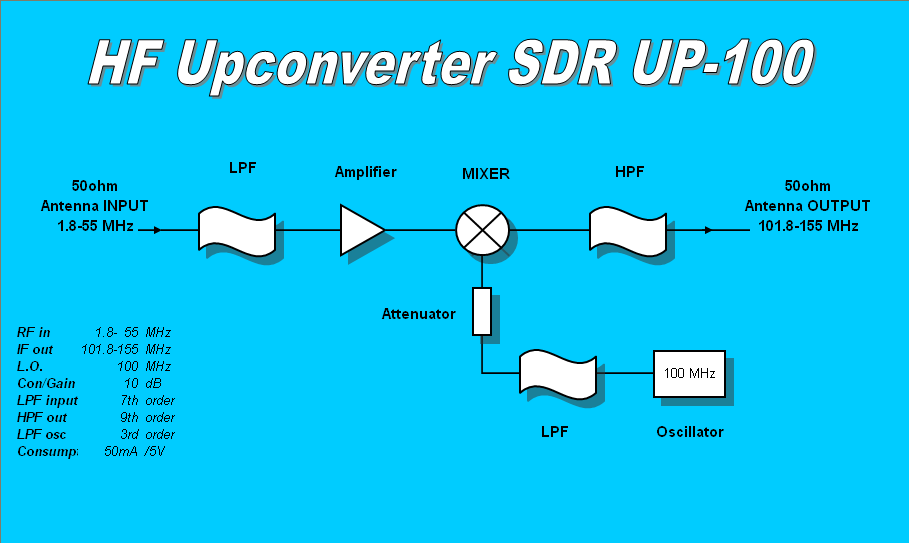
The upconverter is build around double balanced passive level 8dB mixer. For the local oscillator we choose canned oscillator with the round value of 100 MHz to make the calculation easier. At the input there is a 7th order low pass filter and at the output we add the 9th order high pass filter. Another low pass filter is just after the 100 MHz L.O. To cover the losses in the filters and mixer a small MMIC amplifier was inserted resulting with the 10dB of the total system conversion gain.

The upconverter is assembled using mostly the SMD components (except the 5V voltage regulator and canned oscillator) on the high quality FR-4 double sided professionally made PCB measuring only 60x38mm. All precaution was adopted regarding the design and placement of components and good grounding and high quality via system is in place to prevent any unwanted self oscillation. Canned 100MHz L.O. is placed on the ground side of the PCB to reduce to the minimum the leakage of the signal and influence to the input and output signal.
As the PCB is quite small, there was no place to accommodate standard SO-239 or BNC type connectors and the choice was female SMA connector. At the end this is even better solution because the are cheaper and much easier to assemble comparing to BNC or PL-239 type. Small jumper with RG-174 should be final solution.
Power connector is standard 2 pin socket. On board there is 100mA 5V voltage regulator so the supply power can be anything between 9-15V DC. Complete consumption is not higher than 50mA so the unit can be powered through the USB port as well with a small modification. 5V should be applied after the voltage regulator on the PCB in this case.
The original design is using SMD coils for the LPF and HPF calculated for the 100 MHz L.O. If somebody would like to experiment with other I.F. or to replace the input LPF filter with the better BPF (bandpass filters) there is room left for the wire wound coils with the standard through board holes on the PCB. There is also enough place for the capacitors in the input LPF filters because the resulting required value is achieved by connecting two smd capacitors in parallel.
If the amplifier is not required, the MMIC can be simply excluded and the power cut off simply by removing the bias 100 ohm resistor.
At the end, some calculations with the estimated figures where performance of the upconverter can be predicted.
All design and PCB layout is quite flexible leaving enough room to experimenters for playing around the upconverter to experience the SDR world cheap way.
73!